SVG contains the following set of basic shape elements:
Mathematically, these shape elements are equivalent to a 'path' element that would construct the same shape. The basic shapes may be stroked, filled and used as clip paths. All of the properties available for 'path' elements also apply to the basic shapes.
The 'rect' element defines a rectangle which is axis-aligned with the current user coordinate system. Rounded rectangles can be achieved by setting appropriate values for attributes rx and ry.
<!ENTITY % rectExt "" > <!ELEMENT rect (%descTitleMetadata;,(animate|set|animateMotion|animateColor|animateTransform %geExt;%rectExt;)*) > <!ATTLIST rect %stdAttrs; %testAttrs; %langSpaceAttrs; externalResourcesRequired %Boolean; #IMPLIED class %ClassList; #IMPLIED style %StyleSheet; #IMPLIED %PresentationAttributes-FillStroke; %PresentationAttributes-Graphics; transform %TransformList; #IMPLIED %graphicsElementEvents; x %Coordinate; #IMPLIED y %Coordinate; #IMPLIED width %Length; #REQUIRED height %Length; #REQUIRED rx %Length; #IMPLIED ry %Length; #IMPLIED > |
Attribute definitions:
If a properly specified value is provided for rx but not for ry, then the user agent processes the 'rect' element with the effective value for ry as equal to rx. If a properly specified value is provided for ry but not for rx, then the user agent processes the 'rect' element with the effective value for rx as equal to ry. If neither rx nor ry has a properly specified value, then the user agent processes the 'rect' element as if no rounding had been specified, resulting in square corners. If rx is greater than half of the width of the rectangle, then the user agent processes the 'rect' element with the effective value for rx as half of the width of the rectangle. If ry is greater than half of the height of the rectangle, then the user agent processes the 'rect' element with the effective value for ry as half of the height of the rectangle.
Mathematically, a 'rect' element can be mapped to an equivalent 'path' element as follows: (Note: all coordinate and length values are first converted into user space coordinates according to Processing rules when using absolute unit identifiers and percentages.)
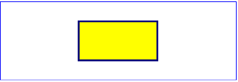
Example rect01 below expresses all values in physical units (centimeters, in this case). The 'rect' element is filled with yellow and stroked with navy.
<?xml version="1.0" standalone="no"?>
<!DOCTYPE svg PUBLIC "-//W3C//DTD SVG 20000802//EN"
  "http://www.w3.org/TR/2000/CR-SVG-20000802/DTD/svg-20000802.dtd">
<svg width="12cm" height="4cm">
  <desc>Example rect01 - rectangle expressed in physical units</desc>

  <rect x="4cm" y="1cm" width="4cm" height="2cm"
        style="fill:yellow; stroke:navy; stroke-width:0.1cm" />
</svg>
 |
View this example as SVG (SVG-enabled browsers only)
Example rect02 below specifies the coordinates of the two rounded rectangles in the user coordinate system established by the viewBox attribute on the 'svg' element and the transform attribute on the 'g' element. The rx specifies how to round the corners of the rectangles. Note that since no value has been specified for the ry attribute, it will be assigned the same value as the rx attribute.
<?xml version="1.0" standalone="no"?>
<!DOCTYPE svg PUBLIC "-//W3C//DTD SVG 20000802//EN"
  "http://www.w3.org/TR/2000/CR-SVG-20000802/DTD/svg-20000802.dtd">
<svg width="12cm" height="4cm" viewBox="0 0 1200 400">
  <desc>Example rect02 - rounded rectangles expressed in user coordinates</desc>

  <rect x="1" y="1" width="1198" height="398"
        style="fill:none; stroke:blue"/>

  <rect x="100" y="100" width="400" height="200" rx="50"
        style="fill:green;" />

  <g transform="translate(700 210) rotate(-30)">
    <rect x="0" y="0" width="400" height="200" rx="50"
          style="fill:none; stroke:purple; stroke-width:30" />
  </g>
</svg>
 |
View this example as SVG (SVG-enabled browsers only)
The 'circle' element defines a circle based on a center point and a radius.
<!ENTITY % circleExt "" > <!ELEMENT circle (%descTitleMetadata;,(animate|set|animateMotion|animateColor|animateTransform %geExt;%circleExt;)*) > <!ATTLIST circle %stdAttrs; %testAttrs; %langSpaceAttrs; externalResourcesRequired %Boolean; #IMPLIED class %ClassList; #IMPLIED style %StyleSheet; #IMPLIED %PresentationAttributes-FillStroke; %PresentationAttributes-Graphics; transform %TransformList; #IMPLIED %graphicsElementEvents; cx %Coordinate; #IMPLIED cy %Coordinate; #IMPLIED r %Length; #REQUIRED > |
Attribute definitions:
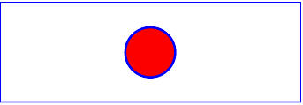
Example circle01 below expresses all values in physical units (centimeters, in this case). The 'circle' element is filled with red and stroked with blue.
<?xml version="1.0" standalone="no"?>
<!DOCTYPE svg PUBLIC "-//W3C//DTD SVG 20000802//EN"
  "http://www.w3.org/TR/2000/CR-SVG-20000802/DTD/svg-20000802.dtd">
<svg width="12cm" height="4cm">
  <desc>Example circle01 - circle expressed in physical units</desc>

  <circle cx="6cm" cy="2cm" r="1cm"
        style="fill:red; stroke:blue; stroke-width:0.1cm" />
</svg>
 |
View this example as SVG (SVG-enabled browsers only)
The 'ellipse' element defines an ellipse which is axis-aligned with the current user coordinate system based on a center point and two radii.
<!ENTITY % ellipseExt "" > <!ELEMENT ellipse (%descTitleMetadata;,(animate|set|animateMotion|animateColor|animateTransform %geExt;%ellipseExt;)*) > <!ATTLIST ellipse %stdAttrs; %testAttrs; %langSpaceAttrs; externalResourcesRequired %Boolean; #IMPLIED class %ClassList; #IMPLIED style %StyleSheet; #IMPLIED %PresentationAttributes-FillStroke; %PresentationAttributes-Graphics; transform %TransformList; #IMPLIED %graphicsElementEvents; cx %Coordinate; #IMPLIED cy %Coordinate; #IMPLIED rx %Length; #REQUIRED ry %Length; #REQUIRED > |
Attribute definitions:
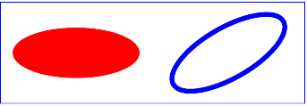
Example ellipse01 below specifies the coordinates of the two ellipses in the user coordinate system established by the viewBox attribute on the 'svg' element and the transform attribute on the 'g' and 'ellipse' elements. Both ellipses use the default values of zero for the cx and cy attributes (the center of the ellipse). The second ellipse is rotated.
<?xml version="1.0" standalone="no"?>
<!DOCTYPE svg PUBLIC "-//W3C//DTD SVG 20000802//EN"
  "http://www.w3.org/TR/2000/CR-SVG-20000802/DTD/svg-20000802.dtd">
<svg width="12cm" height="4cm" viewBox="0 0 1200 400">
  <desc>Example ellipse01 - ellipses expressed in user coordinates</desc>

  <g transform="translate(300 200)">
    <ellipse rx="250" ry="100"
          style="fill:red" />
  </g>

  <ellipse transform="translate(900 200) rotate(-30)"
        rx="250" ry="100"
        style="fill:none; stroke:blue; stroke-width: 20" />

</svg>
 |
View this example as SVG (SVG-enabled browsers only)
The 'line' element defines a line segment that starts at one point and ends at another.
<!ENTITY % lineExt "" > <!ELEMENT line (%descTitleMetadata;,(animate|set|animateMotion|animateColor|animateTransform %geExt;%lineExt;)*) > <!ATTLIST line %stdAttrs; %testAttrs; %langSpaceAttrs; externalResourcesRequired %Boolean; #IMPLIED class %ClassList; #IMPLIED style %StyleSheet; #IMPLIED %PresentationAttributes-FillStroke; %PresentationAttributes-Graphics; %PresentationAttributes-Markers; transform %TransformList; #IMPLIED %graphicsElementEvents; x1 %Coordinate; #IMPLIED y1 %Coordinate; #IMPLIED x2 %Coordinate; #IMPLIED y2 %Coordinate; #IMPLIED > |
Attribute definitions:
Mathematically, a 'line' element can be mapped to an equivalent 'path' element as follows: (Note: all coordinate and length values are first converted into user space coordinates according to Processing rules when using absolute unit identifiers and percentages.)
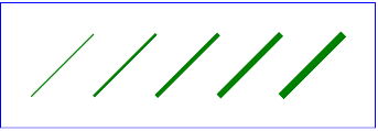
Example line01 below specifies the coordinates of the five lines in the user coordinate system established by the viewBox attribute on the 'svg' element. The lines have different thicknesses.
<?xml version="1.0" standalone="no"?>
<!DOCTYPE svg PUBLIC "-//W3C//DTD SVG 20000802//EN"
  "http://www.w3.org/TR/2000/CR-SVG-20000802/DTD/svg-20000802.dtd">
<svg width="12cm" height="4cm" viewBox="0 0 1200 400">
  <desc>Example line01 - lines expressed in user coordinates</desc>

  <g style="fill:none; stroke:green">
    <line x1="100" y1="300" x2="300" y2="100"
            style="stroke-width:5" />
    <line x1="300" y1="300" x2="500" y2="100"
            style="stroke-width:10" />
    <line x1="500" y1="300" x2="700" y2="100"
            style="stroke-width:15" />
    <line x1="700" y1="300" x2="900" y2="100"
            style="stroke-width:20" />
    <line x1="900" y1="300" x2="1100" y2="100"
            style="stroke-width:25" />
  </g>
</svg>
 |
View this example as SVG (SVG-enabled browsers only)
The 'polyline' element defines a set of connected straight line segments. Typically, 'polyline' elements define open shapes.
<!ENTITY % polylineExt "" > <!ELEMENT polyline (%descTitleMetadata;,(animate|set|animateMotion|animateColor|animateTransform %geExt;%polylineExt;)*) > <!ATTLIST polyline %stdAttrs; %testAttrs; %langSpaceAttrs; externalResourcesRequired %Boolean; #IMPLIED class %ClassList; #IMPLIED style %StyleSheet; #IMPLIED %PresentationAttributes-FillStroke; %PresentationAttributes-Graphics; %PresentationAttributes-Markers; transform %TransformList; #IMPLIED %graphicsElementEvents; points %Points; #REQUIRED > |
Attribute definitions:
If an odd number of coordinates is provided, then the element is in error, with the same user agent behavior as occurs with an incorrectly specified 'path' element.
Mathematically, a 'polyline' element can be mapped to an equivalent 'path' element as follows: (Note: all coordinate and length values are first converted into user space coordinates according to Processing rules when using absolute unit identifiers and percentages.)
Example polyline01 below specifies a polyline in the user coordinate system established by the viewBox attribute on the 'svg' element.
<?xml version="1.0" standalone="no"?>
<!DOCTYPE svg PUBLIC "-//W3C//DTD SVG 20000802//EN"
  "http://www.w3.org/TR/2000/CR-SVG-20000802/DTD/svg-20000802.dtd">
<svg width="12cm" height="4cm" viewBox="0 0 1200 400">
  <desc>Example polyline01 - increasingly larger bars</desc>

  <rect x="1" y="1" width="1198" height="398"
        style="fill:none; stroke:blue"/>
  <polyline style="fill:none; stroke:blue; stroke-width:10"
            points="50,375
                    150,375 150,325 250,325 250,375
                    350,375 350,250 450,250 450,375
                    550,375 550,175 650,175 650,375
                    750,375 750,100 850,100 850,375
                    950,375 950,25 1050,25 1050,375
                    1150,375" />
</svg>
 |
View this example as SVG (SVG-enabled browsers only)
The 'polygon' element defines a closed shape consisting of a set of connected straight line segments.
<!ENTITY % polygonExt "" > <!ELEMENT polygon (%descTitleMetadata;,(animate|set|animateMotion|animateColor|animateTransform %geExt;%polygonExt;)*) > <!ATTLIST polygon %stdAttrs; %testAttrs; %langSpaceAttrs; externalResourcesRequired %Boolean; #IMPLIED class %ClassList; #IMPLIED style %StyleSheet; #IMPLIED %PresentationAttributes-FillStroke; %PresentationAttributes-Graphics; %PresentationAttributes-Markers; transform %TransformList; #IMPLIED %graphicsElementEvents; points %Points; #REQUIRED > |
Attribute definitions:
If an odd number of coordinates is provided, then the element is in error, with the same user agent behavior as occurs with an incorrectly specified 'path' element.
Mathematically, a 'polygon' element can be mapped to an equivalent 'path' element as follows: (Note: all coordinate and length values are first converted into user space coordinates according to Processing rules when using absolute unit identifiers and percentages.)
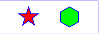
Example polygon01 below specifies two polygons (a star and a hexagon) in the user coordinate system established by the viewBox attribute on the 'svg' element.
<?xml version="1.0" standalone="no"?>
<!DOCTYPE svg PUBLIC "-//W3C//DTD SVG 20000802//EN"
  "http://www.w3.org/TR/2000/CR-SVG-20000802/DTD/svg-20000802.dtd">
<svg width="12cm" height="4cm" viewBox="0 0 1200 400">
  <desc>Example polygon01 - star and hexagon</desc>

  <polygon style="fill:red; stroke:blue; stroke-width:10"
            points="350,75  379,161 469,161 397,215
                    423,301 350,250 277,301 303,215
                    231,161 321,161" />
  <polygon style="fill:lime; stroke:blue; stroke-width:10"
            points="850,75  958,137.5 958,262.5
                    850,325 742,262.6 742,137.5" />
</svg>
 |
View this example as SVG (SVG-enabled browsers only)
The following is the Backus-Naur Form (BNF) for points specifications in 'polyline' and 'polygon' elements. The following notation is used:
list-of-points:
    wsp* coordinate-pairs? wsp*

coordinate-pairs:
    coordinate-pair
    | coordinate-pair comma-wsp coordinate-pairs

coordinate-pair:
    coordinate comma-wsp coordinate

coordinate:
    number

number:
    sign? integer-constant
    | sign? floating-point-constant

comma-wsp:
    (wsp+ comma? wsp*) | (comma wsp*)

comma:
    ","

integer-constant:
    digit-sequence

floating-point-constant:
    fractional-constant exponent?
    | digit-sequence exponent

fractional-constant:
    digit-sequence? "." digit-sequence
    | digit-sequence "."

exponent:
    ( "e" | "E" ) sign? digit-sequence

sign:
    "+" | "-"

digit-sequence:
    digit
    | digit digit-sequence

digit:
    "0" | "1" | "2" | "3" | "4" | "5" | "6" | "7" | "8" | "9"

wsp:
    (#x20 | #x9 | #xD | #xA)+
The following interfaces are defined below: SVGRectElement, SVGCircleElement, SVGEllipseElement, SVGLineElement, SVGAnimatedPoints, SVGPolylineElement, SVGPolygonElement.
The SVGRectElement interface corresponds to the 'rect' element.
interface SVGRectElement :
                SVGElement,
                SVGTests,
                SVGLangSpace,
                SVGExternalResourcesRequired,
                SVGStylable,
                SVGTransformable,
                events::EventTarget {

  readonly attribute SVGAnimatedLength x;
  readonly attribute SVGAnimatedLength y;
  readonly attribute SVGAnimatedLength width;
  readonly attribute SVGAnimatedLength height;
  readonly attribute SVGAnimatedLength rx;
  readonly attribute SVGAnimatedLength ry;
};
The SVGCircleElement interface corresponds to the 'rect' element.
interface SVGCircleElement :
                SVGElement,
                SVGTests,
                SVGLangSpace,
                SVGExternalResourcesRequired,
                SVGStylable,
                SVGTransformable,
                events::EventTarget {

  readonly attribute SVGAnimatedLength cx;
  readonly attribute SVGAnimatedLength cy;
  readonly attribute SVGAnimatedLength r;
};
The SVGEllipseElement interface corresponds to the 'ellipse' element.
interface SVGEllipseElement :
                SVGElement,
                SVGTests,
                SVGLangSpace,
                SVGExternalResourcesRequired,
                SVGStylable,
                SVGTransformable,
                events::EventTarget {

  readonly attribute SVGAnimatedLength cx;
  readonly attribute SVGAnimatedLength cy;
  readonly attribute SVGAnimatedLength rx;
  readonly attribute SVGAnimatedLength ry;
};
The SVGLineElement interface corresponds to the 'line' element.
interface SVGLineElement :
                SVGElement,
                SVGTests,
                SVGLangSpace,
                SVGExternalResourcesRequired,
                SVGStylable,
                SVGTransformable,
                events::EventTarget {

  readonly attribute SVGAnimatedLength x1;
  readonly attribute SVGAnimatedLength y1;
  readonly attribute SVGAnimatedLength x2;
  readonly attribute SVGAnimatedLength y2;
};
The SVGAnimatedPoints interface supports elements which have a 'points' attribute which holds a list of coordinate values and which support the ability to animate that attribute.
Additionally, the 'points' attribute on the original element accessed via the XML DOM (e.g., using the getAttribute() method call) will reflect any changes made to points.
interface SVGAnimatedPoints {

  readonly attribute SVGList   points;
  readonly attribute SVGList   animatedPoints;
};
Provides access to the base (i.e., static) contents of the points attribute.
The various methods from SVGList, which are defined to accept parameters and return values of type Object, must receive parameters of type SVGPoint and return values of type SVGPoint.
Provides access to the current animated contents of the points attribute. If the given attribute or property is being animated, contains the current animated value of the attribute or property. If the given attribute or property is not currently being animated, contains the same value as 'points'.
The various methods from SVGList, which are defined to accept parameters and return values of type Object, must receive parameters of type SVGPoint and return values of type SVGPoint.
The SVGPolylineElement interface corresponds to the 'polyline' element.
interface SVGPolylineElement :
                SVGElement,
                SVGTests,
                SVGLangSpace,
                SVGExternalResourcesRequired,
                SVGStylable,
                SVGTransformable,
                events::EventTarget,
                SVGAnimatedPoints {};
The SVGPolygonElement interface corresponds to the 'polygon' element.
interface SVGPolygonElement :
                SVGElement,
                SVGTests,
                SVGLangSpace,
                SVGExternalResourcesRequired,
                SVGStylable,
                SVGTransformable,
                events::EventTarget,
                SVGAnimatedPoints {};