As more electronic devices with pen interfaces have and continue
to become available for entering and manipulating information,
applications need to be more effective at leveraging this method of
input. Handwriting is an input modality that is very familiar for
most users since everyone learns to write in school. Hence, users
will tend to use this as a mode of input and control when
available.
A pen-based interface is enabled by a transducer device and a
pen that allow movements of the pen to be captured as digital ink.
Digital ink can be passed on to recognition software that will
convert the pen input into appropriate computer actions.
Alternatively, the handwritten input can be organized into ink
documents, notes or messages that can be stored for later retrieval
or exchanged through telecommunications means. Such ink documents
are appealing because they capture information as the user composed
it, including text in any mix of languages and drawings such as
equations and graphs.
Hardware and software vendors have typically stored and
represented digital ink using proprietary or restrictive formats.
The lack of a public and comprehensive digital ink format has
severely limited the capture, transmission, processing, and
presentation of digital ink across heterogeneous devices developed
by multiple vendors. In response to this need, the Ink Markup
Language (InkML) provides a simple and platform-neutral data format
to promote the interchange of digital ink between software
applications.
InkML supports a complete and accurate representation of digital
ink. For instance, in addition to the pen position over time, InkML
allows recording of information about transducer device
characteristics and detailed dynamic behavior to support applications
such as handwriting recognition and authentication. For example,
there is support for recording additional channels such as pen tilt,
or pen tip force (commonlyoften referred to as pressure in
manufacturers' documentation).
InkML provides means for extension. By virtue of being an
XML-based language, users may easily add application-specific
information to ink files to suit the needs of the application at
hand.
With the establishment of a non-proprietary ink standard, a
number of applications, old and new, are expanded where the pen can
be used as a very convenient and natural form of input. Here are a
few examples.
The current InkML specification defines a set of primitive
elements sufficient for all basic ink applications. Few semantics
are attached to these elements. All content of an InkML document is
contained within a single <ink> element. The
fundamental data element in an InkML file is the
<trace>. A trace represents a sequence of
contiguous ink points -- e.g., the X and Y coordinates of the pen's
position. A sequence of traces accumulates to meaningful units,
such as characters and words. The <traceFormat>
element is used to define the format of data within a trace.
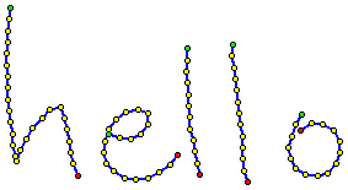
These traces consist simply of alternating X and Y values, and
may look like this when rendered:
Figure 1 shows a trace of a sampled handwriting signal
representing. The dots mark the sampling positions which were
interpolated by the blue line. Green points represent pen-downs
whereas red dots indicate pen-ups.
Information about the transducer device used to collect the ink
(e.g., the sampling rate and resolution) is specified with the
<captureDevice> element. The Multimodal
Interaction Working Group is currently working with the Device
Independence Working Group to make sure that transducer
characteristics are also represented as a CC/PP profile that can be
included inside an InkML document by reference. See [CC/PP].
Ink traces can have certain attributes such as color and width.
These and other attributes are captured using the
<brush> element. Traces that share the same
characteristics, such as being written with the same brush, can be
grouped together with the <traceGroup>
element.
For applications that require ink sharing, such as collaborative
whiteboards, where ink coming from different devices is drawn on a
common canvas, the <context> element allows
representation and grouping of the pertinent information, such as
the trace format, brush, and canvas.
In all appropriate cases, the InkML specification defines
default values for elements that are not specified, and rules that
establish the scope of a given attribute.
Application-specific elements are expected to be defined to
provide a higher-level description of the digital ink captured in
the primitive elements. Some application-specific elements would
reference the primitive elements. For example, a page tag may be
useful in a document management application to indicate groups of
traces belonging to a particular page. In a form processing
application, a field tag might indicate a group of traces belonging
to a particular field. Another example of an application-specific
element is <writerInfo> which could be used to
record information about the age and handedness of the writer.
Finally, the InkML specification is currently restricted to
fixed Cartesian coordinate systems. Similarly, it does not support
non-ink events (although these could be handled via
application-specific elements), or sophisticated compression of
trace data.
Most ink-related applications fall into two broad categories:
Streaming and Archival. Archival ink applications capture and store
digital ink for later processing, such as document
storage/retrieval applications and remote on-line forms processing
(where forms are filled on electronic tablet computers and
processed remotely). In these applications, all primitive elements
are written prior to processing. For ease of processing, it is
recommended that, in archival mode, referenced elements be defined
inside of a declaration block using the <defs>
element.
Streaming ink applications, on the other hand, capture and
transmit digital ink in essentially real time, such as in the
electronic whiteboard example mentioned above. In order to support
a streaming style of ink markup generation, the InkML language
supports the notion of a "current" state (e.g., the current brush)
and allows for incremental changes to this state.
Traces are the basic element used to record the trajectory of
the pen as the user writes digital ink. More specifically, these
recordings describe sequences of connected points. On most devices,
these sequences of points will be bounded by pen contact change
events (pen-up and pen-down), although some devices may simply
record proximity and force data without providing an interpretation
of pen-up or pen-down state.
The simplest form of encoding specifies the X and Y coordinates of
each sample point. For compactness, it may be desirable to specify
absolute coordinates only for the first point in the trace and use
delta-x and delta-y values to encode subsequent points. Some devices
record acceleration rather than absolute or relative position; some
provide additional data that may be encoded in the trace, including Z
coordinates or tip force (pressure), or
the state of side switches or buttons.
These variations in the information available from different
capture devices, or needed by different applications, are supported
in InkML through the <traceFormat> and
<trace> elements. The
<traceFormat> element specifies the encoding
format for each sample of a recorded trace, while
<trace> elements are used to represent the
actual trace data. If no <traceFormat> is
specified, a default encoding format of X and Y coordinates is
assumed.
Traces generated by different devices, or used in differing
applications, may contain different types of information. InkML
defines channels to describe the data that may be encoded
in a trace.
A channel can be characterized as either regular--meaning that
its value is recorded for every sample point of the trace, or
intermittent--meaning that its value may change infrequently and
thus will not necessarily be recorded for every sample point. X and
Y coordinates are examples of likely regular channels, while the
state of a pen button is likely to be an intermittent channel.
- regularChannels?
intermittentChannels?
The <traceFormat> element describes the
format used to encode points within <trace>
elements. In particular, it defines the sequence of channel values
that occurs within <trace> elements. The order
of declaration of channels in the <traceFormat>
element determines the order of appearance of their values within
<trace> elements. X and Y should be the first
two channels of the <traceFormat> if they are
used.
Regular channels appear first in the <trace>,
followed by any intermittent channels. Correspondingly, the
<traceFormat> element contains a
<regularChannels> section followed by an
<intermittentChannels> section. If no channels
of a specific type exist, the corresponding element may be
omitted.
3.1.2 <regularChannels> element
Attributes:
none
Contents:
The <regularChannels> element lists those
channels whose value must be recorded for each sample point. The
order of the channel declarations within the
<regularChannels> element specifies the order in
which the channel data samples appear within
<trace> elements which use this format.
3.1.3 <intermittentChannels> element
none
The <intermittentChannels> lists those
channels whose value may optionally be recorded for each sample
point. As with the <regularChannels> element,
the order of the enclosed channel declaractions gives the order of
the intermittent channel data samples within traces having this
format.
3.1.4 <channel> element
name = xsd:ID
The name of this channel.
Required: yes
type = "integer" | "decimal" | "boolean"
The data type of the point values for this
channel.
Required: no, Default: "decimal"
default = xsd:decimal | xsd:boolean
The data type of the point values for this
channel.
Required: no, Default: 0 (for integer or decimal
channel), false (for boolean channel)
Within a <regularChannels> or
<intermittentChannels> element, channels are
described using the <channel> element, with
name, type, and default attributes.
The required name attribute specifies the interpretation
of the channel in the trace data. The following channel names, with
their specified meanings, are reserved:
| channel name |
interpretation |
| X |
X coordinate (horizontal pen position) |
| Y |
Y coordinate (vertical pen position) |
| Z |
Z coordinate (height of pen above paper/digitizer) |
| F |
pen tip force (tablet pressure) |
| S |
tip switch state (touching/not touching the
digitizer) |
| B1...Bn |
side button states |
| Tx |
tilt along the x-axis |
| Ty |
tilt along the y-axis |
| A |
azimuth angle of the pen (yaw) |
| E |
elevation angle of the pen (pitch) |
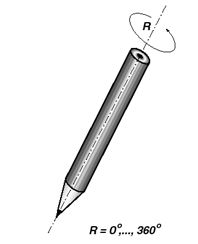
| R |
rotation (rotation about pen axis - i.e., like the roll axis of
an airplane) |
| T |
time (of the sample point) |
The type attribute defines the encoding type for the
channel (either boolean, decimal, or integer). If type is
not specified, it defaults to decimal.
A default value can be specified for the channel using the
default attribute; the use of default values within a trace
is described in the next section. If no default is
specified, it is assumed to be zero for integer and decimal-valued
channels, and false for boolean channels.
Typically, a channel in the <traceFormat>
will map directly to a corresponding channel provided by the
digitizing device, and its values as recorded in the trace data
will be the original channel values recorded by the device.
However, for some applications, it may be useful to store
normalized channel values instead, or even to remap the channels
provided by the digitizing device to different channels in the
trace data. This correspondence between the trace data and the
device channels is recorded using a <mapping>
element within the <channel> element.
The <mapping> element can specify the
identity mapping, or a formula expressed in MathML, or a lookup
table. For a detailed description of the types of mappings
supported by the <mapping> element and its
usage, see the Mappings section.
If no mapping is specified for a channel, it is assumed to be
unknown.
3.1.5 Orientation Channels
The channels Tx, Ty, A, E and R are defined for recording of pen
orientation data. Implementers may choose to use either pen azimuth
A and pen elevation E, or alternatively tilt angles Tx and Ty. The
latter are the angles of projections of the pen axis onto the XZ
and YZ planes, measured from the vertical. It is often useful to
record the sine of this angle, rather than the angle itself, as
this is usually more useful in calculations involving angles. The
<mapping> element described in the Mappings section can be employed to specify an applied
sine transformation.
The third degree of freedom in orientation is generally defined
as the rotation of the pen about its axis. This is potentially
useful (in combination with tilt) in application such as
illustration or calligraphy, and signature verification.
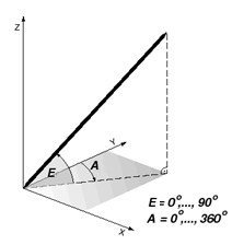
Figure 2a displays the pen orientation using Azimuth and
Elevation. The origin of the Azimuth is at the Y-axis. Azimuth
increases anticlockwise up to 360 degrees. The origin of Elevation
is located within the XY-plane. Elevation increases up to 90
degrees, at which point the pen is perpendicular to the
XY-plane.
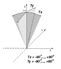
Figure 2b explains the definition of the Tilt-X and the Tilt-Y
angles. For both the origin is along the Z-axis. Tilt-X increases
up to +90 degrees for inclinations along the positive X-axis and
decreases up to -90 degrees for inclinations along the negative
X-axis. Respectively, Tilt-Y is defined for pen inclinations along
the Y-axis.
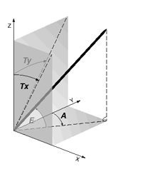
Figure 3a displays the pen orientation decomposition as
functions of Azimuth/Elevation or alternatively as function of
Tilt-X/Tilt-Y. Thereby, Elevations of the pen which are mapped to
the XZ- and to the YZ- plane lead to Tilt-X and Tilt-Y.
Figure 3b shows the Rotation of the pen along its longitudinal
axis.
3.1.6 Time Channel
The time channel allows for detailed recording of the timing
information for each sample point within a trace. This can be
useful if the digitizing device has a non-uniform sampling rate,
for example, or in cases where duplicate point data is removed for
the sake of compactness.
The time channel can be specified as either a regular or
intermittent channel. When specified as a regular channel, the single
quote prefix can be used to record incremental time between successive
points. Otherwise, the value of the time channel for a given sample
point is defined to be the timestamp of that point in the units and
frame of reference specified by its corresponding
<captureDevice> description (more precisely, by the
<channelDef> element for
the channel).
As with the other predefined channels, the meaning of the
integer or decimal values recorded by the time channel in a given
trace is defined by the <captureDevice>
information associated with the trace's traceFormat. In the case of
the time channel, its <channelDef> element
contains both a units and relativeTo attribute.
The units attribute gives the units of the recorded time
values, and the relativeTo attribute describes the frame of
reference for those recorded values. The value of the
relativeTo attribute can either be an xsd:dateTime or
xsd:time which gives the base timestamp for the time channel values
in every trace, or it can have the value "trace", which means that
the time channel values are relative to the beginning timestamps of
the individual traces in which they appear.
The following example defines a time channel whose values for a
given point are the timestamp of that point in milliseconds since
midnight, January 1, 2003, UTC:
<channelDef name="T">
   <representation type="integer" units="ms"
                   relativeTo="2003-01-01T00:00:00Z"/>
</channelDef>
This <channelDef> element defines a time
channel whose values are the timestamp in milliseconds for a
particular point offset from the beginning timestamp of the trace
(see the section timestamps section for a description of trace timestamping):
<channelDef name="T">
   <representation type="integer" units="ms" relativeTo="trace"/>
</channelDef>
If no <captureDevice> information is
provided, or if no value is specified for the relativeTo
attribute, the ink processor cannot make any assumption about the
relative timing of points within different traces. Likewise, if no
units are specified, no assumption can be made about the units of
the time channel data.
3.1.7 User Defined Channels
In addition, user-defined channels are allowed, although their
interpretation is not required by conforming ink markup
processors.
3.1.8 Specifying Trace Formats
The following example defines a
<traceFormat> which reports decimal-valued X and
Y coordinates for each point, and intermittent boolean values for
the states of two buttons B1 and B2, which have default values of
"false":
<traceFormat id="xyb1b2">
   <regularChannels>
      <channel name="X" type="decimal">
         <mapping type="identity"/>
      </channel>
      <channel name="Y" type="decimal">
         <mapping type="identity"/>
      </channel>
   </regularChannels>
   <intermittentChannels>
      <channel name="B1" type="boolean" default="F">
         <mapping type="identity"/>
      </channel>
      <channel name="B2" type="boolean" default="F">
         <mapping type="identity"/>
      </channel>
   </intermittentChannels>
</traceFormat>
The appearance of a
<traceFormat> element in an ink markup file both
defines the format and installs it as the current format for
subsequent traces (except within a <defs> block). The id
attribute of a <traceFormat> allows the format to
be reused by multiple contexts (see the Context
section). If no <traceFormat> is specified, the
following default format is assumed for all traces:
<traceFormat id="default">
   <regularChannels>
      <channel name="X" type="decimal"/>
      <channel name="Y" type="decimal"/>
   </regularChannels>
</traceFormat>
Thus, in the simplest case, an InkML file may contain nothing
but <trace> elements.
3.2 Traces
3.2.1 <trace> element
id = xsd:ID
The identifier for this trace.
Required: no, Default: none
type = "penDown" | "penUp" | "indeterminate" |
"continuation"
The type of this trace.
Required: no, Default:
"indeterminate"
brushRef = xsd:IDREF
The brush for this trace.
Required: no, Default: none
start = xsd:integer
The absolute timestamp for the start of this
trace, in milliseconds since 1 January 1970 00:00:00 UTC.
Required: no, Default: unknown
duration = xsd:integer
The duration of this trace, in milliseconds.
Required: no, Default: unknown
timeOffset = xsd:integer
The relative timestamp or time-of-day for the
start of this trace, in milliseconds.
Required: no, Default: unknown
timeRef = xsd:anyURI | "*"
The element providing the reference timestamp
for the start time of this trace.
Required: no, Default:
none
The following grammar defines the syntax of the data that
appears within a <trace> element. It is
described in Backus-Naur Form (BNF) using the following
notation:
- *: 0 or more
- +: 1 or more
- ?: 0 or 1
- (): grouping
- |: separates alternatives
- double quotes surround literals
- #x precedes hex character codes
The grammar is as follows:
trace ::=
wsp* point+

point ::=
     regularPart intermittentPart?

regularPart ::=
regularValue+

intermittentPart ::=
     ":" wsp* intermittentValue* ";" wsp*

regularValue ::=
qualifier? value wsp*

intermittentValue ::=
value wsp*

value ::=
integer | decimal | code

integer ::=
sign'-'? digit+

decimal ::=
sign'-'? digit+ "." digit+

code ::=
     "a" | "b" | "c" | "d" | "e" | "f" | "g" | "h" | "i" |
     "j" | "k" | "l" | "m" | "n" | "o" | "p" | "q" | "r" |
     "s" | "t" | "u" | "v" | "w" | "x" | "y" | "z" | "A" |
     "B" | "C" | "D" | "E" | "F" | "G" | "H" | "I" | "J" |
     "K" | "L" | "M" | "N" | "O" | "P" | "Q" | "R" | "S" |
     "T" | "U" | "V" | "W" | "X" | "Y" | "Z" | "*"

digit ::=
     "0" | "1" | "2" | "3" | "4" | "5" | "6" | "7" | "8" | "9"


sign ::=
     "+" | "-"

qualifier ::=
     "!" | "'" | """

wsp ::=
     #x20 | #x9 | #xD | #xA
The number of regularValue
tokens appearing within a trace must match the number of regular
channels specified in the <traceFormat>, and the
number of intermittentValue
tokens must be no greater than the number of intermittent
channels.
Whitespace is optional before and after
regularValue and
intermittentValue tokens
(unless required to separate two adjacent positive integer or
decimal tokens values without + signs).
The <trace> element is used to record the
data captured by the digitizer. It contains a sequence of points
encoded according to the specification given by the
<traceFormat> element.
The type attribute of a <trace>
indicates the pen contact state (either "pen-up" or "pen-down")
during its recording. A value of "indeterminate" is used if the
contact-state is neither pen-up nor pen-down, and may be either
unknown or variable within the trace. For example, a signature may
be captured as a single indeterminate trace containing both the
actual writing and the trajectory of the pen between strokes. A
value of "continuation" means both that the pen contact state is
retained from the previous trace element and that the points of the
current trace element are a temporally contiguous continuation of
(and thus should be connected to) the previous trace element. This
allows a trace to be spread across several elements for purposes
such as streaming.
Regular channels may be reported as explicit values, differences,
or second differences: Prefix symbols are used to indicate the
interpretation of a value: a preceding exclamation point (!) indicates an explicit value,
a single quote (')
indicates a single difference, and a double quote prefix (") indicates a second
difference. If there is no prefix, then the channel value is
interpreted as explicit, difference, or second difference based on the
last prefix for the channel. If there is no last prefix, the value is
interpreted as explicit.
A second difference encoding must be preceded by a single
difference representation; which, in turn, must be preceded with an
explicit encoding.
NOTE: All traces must begin with an explicit value, not with a
first or second difference. This is true of continuation traces as
well. This allows the location and velocity state information to be
discarded at the end of each trace, simplifying parser design.
Intermittent channels are always encoded explicitly, and
prefixes are not allowed.
Both regular and intermittent channels may be encoded with a
wildcard character *. The wildcard character means either that the
value of the channel remains at the previous channel value (if
explicit), or that the channel continues integrating the previous
velocity and acceleration values.
Booleans are encoded as "T" or "F".
For each point in the trace, regular channel values are reported
first in the order given by the <traceFormat>.
If any intermittent values are reported for the point, the set of
intermittent values is preceded by a colon and ended with a
semicolon. Within these delimiters, the intermittent channels are
represented in the order given by the
<traceFormat>. The list may be terminated early
with the semicolon, and the unreported intermittent channels are
interpreted with wildcards.
Here is an example of a trace of 11 points, using
the following traceFormat:
<traceFormat>
   <regularChannels>
      <channel name="X" type="decimal"/>
      <channel name="Y" type="decimal"/>
   </regularChannels>
   <intermittentChannels>
      <channel name="B1" type="boolean" default="F"/>
      <channel name="B2" type="boolean" default="F"/>
   </intermittentChannels>
</traceFormat>

<trace id = "id4525abc">
1125 18432'23'43"7"-8 3-5+7  -3+6+2+6 8+3+6:T;+2+4:*T;+3+6+3-6:FF;
1125 18432'23'43"7"-8 3-5 7  -3 6 2 6 8 3 6:T; 2 4:*T; 3 6 3-6:FF;
</trace>
The trace is interpreted as follows:
| Trace |
X |
Y |
vx |
vy |
B1 |
B2 |
Comments |
| 1125 18432 |
1125 |
18432 |
? |
? |
F |
F |
button default values |
| '23'43 |
1148 |
18475 |
23 |
43 |
F |
F |
velocity values |
| "7"-8 |
1178 |
18510 |
30 |
35 |
F |
F |
acceleration Values |
| 3-5 |
1211 |
18540 |
33 |
30 |
F |
F |
implicit acceleration
whitespace token sep |
| 7 -3 |
1251 |
18567 |
40 |
27 |
F |
F |
optional whitespace |
| 6 2 |
1297 |
18596 |
46 |
29 |
F |
F |
|
| 6 8 |
1349 |
18633 |
52 |
37 |
F |
F |
space instead of + |
| 3 6:T; |
1404 |
18676 |
55 |
43 |
T |
F |
an optional value |
| 2 4:*T; |
1461 |
18723 |
57 |
47 |
T |
T |
wildcard |
| 3 6 |
1521 |
18776 |
60 |
53 |
T |
T |
optional keep last |
| 3-6:FF; |
1584 |
18823 |
63 |
47 |
F |
F |
optionals |
One would not typically see both a "+"and a "space" used as a
separator in the same trace or document, but it is legal.
An ink markup generator might also include additional whitespace
formatting for clarity. The following trace specification is
identical in meaning to the more compact version shown above:
<trace id = "id4525abc">
1125  18432
'23  '43
"7  "-8
3  -5
7  -3
6  2
6  8
3  6  :T;
2  4  :  *T;
3  6
3-6  :F  F;
</trace>
In addition, the alphabetic characters may be used to encode
small negative and positive integer values. These may be
substituted anywhere for an integer value between -25 and +25.
- The characters "a" to "y" are interpreted as -1 through
-25.
- The characters "A" to "Y" are interpreted as 1 through 25.
- "z" and "Z" are interpreted as zero.
Using these shorthand codes, the above trace could be encoded:
<trace id="4525BCD">
1125 18432'W'43"G"hCeGcFBFHCF:T;BD:*T;CFCf:FF;
</trace>
Note that the true and false values for the side buttons use
symbols that are also used to encode numbers. However, they are
unambiguous because of their location.
Note: the trace syntax defined here makes the InkML file sizes (as
well as the XML DOM trees) smaller while keeping the benefits of
XML. However some applications, for instance concerned with
tranporting InkML documents across the Web, might require even smaller
file sizes. It is thus recommended (but not required) that InkML
implementations support the gzip standard compression scheme (see [RFC1952]).
Open Issues
The working group has been inquiring into the compression ratios
achieved with the alternative trace formats, alone and in
combination with gzip. In combination with gzip, the best results
achieve approximately 9 bits per sample, for two channel data,
which is only about 50% worse than compression with binary
compression algorithms.
However, results of approximately 11 to 12 bps can be achieved
using the velocity feature (without the ascii encoding or
acceleration) in combination with gzip. Compression without
velocity encoding results in files more than a factor of two
larger.
On the other hand, if compactness is desired without using
external compression, the addition of acceleration encoding and
"compact" encoding results in approximately 40% smaller
representation than the velocity representation alone.
The working group is currently considering whether, based on
these results, to simplify the range of encoding options, perhaps
retaining only the verbose representation and the velocity
encoding, as this, in combination with general compression schemes,
would achieve approximately 75% of the effectiveness of the more
complex representations.
3.2.2 Timestamps
Timestamping of traces is supported by the start,
duration, timeOffset and
timeRef attributes and the <timestamp>
element. For ease of processing, all timestamps are expressed in
milliseconds. Traces can either be assigned an absolute start time, or
one that is relative to a reference time. This reference time can
either be the timestamp of a previous trace, or a timestamp
established using the <timestamp> element.
When specified on a <trace> element,
the start attribute indicates the absolute timestamp of the
start of the trace in milliseconds since 1 January 1970 00:00:00 UTC.
In the following example, trace t001 has a timestamp of January
1, 2004 at 0:00:00, UTC.
<trace id="t001" start="1072915200000"></trace>
A relative timestamp is specified using the timeOffset attribute
on a trace, along with an accompanying timeRef attribute.
The value of the timeRef attribute must be the URI of a preceding
<trace> or <timestamp>
element, or the value "*" which represents the start time of the
previous <trace>. If the element referenced by
the timeRef attribute has timestamp T0 and the timeOffset
attribute specifies a value T1, then the timestamp of the trace
is given by T0 + T1 (see section 3.2.4 for
examples). The timeRef attribute should not appear on a trace
which either contains a start attribute or does not contain a
timeOffset attribute.
If the timeOffset attribute is specified without a
corresponding timeRef attribute, the value of the
timeOffset is interpreted as the time-of-day for the trace in
milliseconds. The trace t002 below specifies only its
time-of-day, which is 2.01 seconds after 4:30am.
<trace id="t002" timeOffset="16202010">...</trace>
The optional duration attribute is used to record the
duration of a trace in milliseconds. When streaming InkML, the
duration attribute will not be used, since the trace duration
is not known at the time the <trace> tag is
generated; however, this information can be often be computed from the
trace data, and could be added in the transformation from
streaming to archival InkML.
3.2.3 <timestamp> element
id = xsd:ID
The identifier for this reference
timestamp.
Required: yes
time = xsd:integer
The absolute time for this reference timestamp,
in milliseconds since 1 January 1970 00:00:00 UTC.
Required: if timeOffset is not present
timeOffset = xsd:integer
The relative time for this reference timestamp,
in milliseconds.
Required: if time is not present
timeRef = xsd:anyURI
The element providing a reference timestamp
for this reference timestamp.
Required: no, Default:
none
EMPTY
The <timestamp> element establishes a
reference timestamp which can then be used for relative
timestamping of traces.
The three examples below illustrate the establishment of various
reference timestamps. The first <timestamp>
element, ts001, refers to January 2, 2004 at 7:00am, UTC. The
second establishes timestamp ts002 which refers to January 2, 2004
at 7:10am, UTC (10 minutes after the refernce timestamp ts001), and
the third creates ts003 with time January 1, 2004 at 0:00:04.32,
UTC (4.32 seconds after the timestamp of trace t001).
<timestamp id="ts001" time="1073026800000"/>
<timestamp id="ts002" timeOffset="600000" timeRef="ts001"/>
<timestamp id="ts003" timeOffset="4320" timeRef="t001"/>
3.2.4 Relative Timestamps
The following examples show different usages of the
timeRef attribute. Trace t003 has a start time which is 3
minutes after the reference timestamp whose id is ts001,
trace t004 has a start time which is 4 minutes after the start time
of trace t003, and trace t005 has a start time which is 1 minute, 2
seconds after the start time of the previous trace (t004). The
start times shown in the second column assume the trace and
timestamp examples from above.
| trace declaration |
start time |
<trace id="t003" timeOffset="180000"
timeRef="ts001">...</trace>
|
January 1, 2004 at 7:03am, UTC |
<trace id="t004" timeOffset="240000"
timeRef="t003">...</trace>
|
January 1, 2004 at 7:07am, UTC |
<trace id="t005" timeOffset="62000"
timeRef="*">...</trace>
|
January 1, 2004 at 7:08:02am, UTC |
The following table summarizes the interpretation of trace start
times and reference timestamps for various combinations of the
start, timeOffset and timeRef attributes. Note
that not all combinations are valid:
| |
no timeRef |
timeRef |
| start |
absolute |
invalid |
| timeOffset |
time of day |
relative |
Parsing note: The format of the time attribute can be
determined using the following method (assuming it is a valid
instance of one of the three types):
if the first character is a 'P',
    the time is an xsd:duration,
else if the first character is a '+' or '-',
    the time is an xsd:dateTime,
else if the third character is a digit,
    the time is an xsd:dateTime,
else
    the time is an xsd:time
Open Issue
There is currently some discussion about whether to make
continuation a separate attribute, rather than a type. This
would allow specification of whether a continuation trace was
pen-up, pen-down, or indeterminate in addition to the fact that it
is a continuation.
3.2.5 <traceGroup> element
id = xsd:ID
The identifier for this traceGroup.
Required: no, Default: none
contextRef = xsd:IDREF
The context associated with this
traceGroup.
Required: no, Default: none
brushRef = xsd:IDREF
The brush associated with this
traceGroup.
Required: no, Default: none
The <traceGroup> element is used to group
successive traces which share common characteristics, such as the
same <traceFormat>. The brush and context
sections describe other contextual values that can be specified for
a <traceGroup>. In the following example the two
traces enclosed in the <traceGroup> share the
same brush (see the Brushes section for a
description of brushes).
<traceGroup brushRef="penA">
   <trace>...</trace>
   <trace>...</trace>
</traceGroup>
The use of <traceGroup> is reserved for the
containment of traces according to their properties at the time of
capture. The element may not be nested, and it is not meant to be a
generic grouping mechanism for the semantic labelling of traces. For
that purpose, InkML provides the <traceRef> element.
Trace groups are the primary mechanism for assigning
<context> to traces in archival ink markup. For
additional details about this usage, see the Archival Applications section.
4 Context Elements
A number of device, data format, and coordinate system details
comprise the context in which ink is written and recorded. These
contextual details need to be captured by the ink markup language
in order to fully characterize the recorded ink data.
The <context> element)
provides various attributes such as canvas and
traceFormatRef by which InkML addresses this need. In addition,
the <captureDevice>
element describes how InkML allows accurate recording of the hardware
characteristics relevant during the capture of the ink traces.
Different pen tips (e.g. eraser vs. writing end) or entirely
different pens, physical or virtual, may be used on the same input
device. These details are captured using the
<brush> element.
The following sections describe the elements which are used to
capture the context in which the ink data was recorded.
4.1 Capture Device
One of the important requirements for the ink format is to allow
accurate recording of meta-data about
the hardware that was used to acquire the ink contained in a
file. This is accomplished in the <captureDevice>
block, which may contain either very basic information, or very
detailed information about a number of device characteristics.
Some of these characteristics are already commonly used in
digitizer specifications, while others are somewhat more esoteric, but
nonetheless potentially very useful. Most digitizer manufacturers do
not spec them, and many are not able to measure them. However, these
device characteristics influence signal fidelity and impose some
limits on how the data can be used. Hopefully by beginning to
standardize the recording of these characteristics, we can raise
awareness and encourage device manufacturers to take them into
consideration.
4.1.1 <captureDevice> element
id = xsd:ID
The unique identifier for this
captureDevice element.
Required: yes
manufacturer = xsd:string
String identifying the digitizer device
manufacturer.
Required: no, Default: unknown
model = xsd:string
String identifying the digitizer model.
Required: no, Default: unknown
sampleRate = xsd:decimal
The basic sample rate in samples/sec.
Required: no, Default: unknown
uniform = xsd:boolean
Is the sample rate consistent, with no dropped
points?
Required: no, Default: unknown
latency = xsd:decimal
The basic device latency that applies to all
channels, in milliseconds.
Required: no, Default: unknown
<captureDevice id="foo"
                manufacturer="AcmePen"
                model="FooBar 2000 USB"
                sampleRate="100"
                uniform="TRUE"
                latency="50">

   <channelList>
      ...

   </channelList>
</captureDevice>
The <captureDevice> element will allow
specification of:
- Manufacturer and model
- Basic sampling rate - samples/sec
- Sampling uniformity: must be designated non-uniform if
any pen-down points are skipped or if the sampling is
irregular
- Latency: latency of the real-time channel, in msec, from
physical action to the API time stamp. This is typically specified
at the device level, since all channels often are subject to a
common processing and communications latency.
- Channel List
The <captureDevice> block, including
<channelList>, will often be specified by
reference to a separate xml document, either local or at some
remote URI. Ideally, <captureDevice> blocks for
common devices will become publicly available.
4.1.2 <channelList> element
id = xsd:ID
The unique identifier for this channel
list.
Required: no, Default: none
<channelList id="foo">
   <channelDef name="X">
      ...

   </channelDef>
</channelList>
The <channelList> element lists all data
channels that the device is capable of reporting. Channels
include:
- X coordinate (horizontal pen position, relative or
absolute)
- Y coordinate (up/down or vertical pen position, relative or
absolute)
- Z coordinate (height of pen above paper/digitizer, relative or
absolute)
- Force (pen tip force) [NOTE: this is often referred to as
"pressure" by manufacturers]
- Tip switch state (touching, not touching digitizer)
- Side switches and Buttons (for example, bezel buttons, cursor
buttons...)
- Tilt angle in X dimension
- Tilt angle in Y dimension
- Pen Azimuth (alternative to tilt)
- Pen Elevation (alternative to tilt)
- Pen Rotation (around the pen axis)
In addition, devices may define their own data channels for the
recording of device-specific information.
4.1.3 <channelDef> element
name = xsd:NMTOKENS
The name of the channel described by this
<channelDef> element.
Required: yes
<channelDef name="S">
   <representation  type="boolean"/>
   <threshold       value="0.1" units="newtons"/>
   <skew          value="5" units="msec"/>
</channelDef>

<channelDef name="X">
   <representation  type="integer"/>
   <range           min="0" max="8191"/>
   <resolution    value="0.1"  units="mm"/>
   <quantization  value="0.01" units="mm"/>
   <noise         value="0.05" units="mm"/>
   <accuracy      value="0.5"  units="mm"/>
   <crossCoupling>
      <bind source="Tx"/>
      <bind source="Ty"/>
      <mapping type="mathml" apply="relative">
         <math>
         ...
         </math>
      </mapping>
   </crossCoupling>
   <skew          value="2" units="msec"/>
   <minBandwidth  value="15.0"/>
   <distortion    value=".001"/>

</channelDef>
For each data channel that a device is capable of reporting, its
characteristics are described using a
<channelDef> element. Each channel may specify
any of the following when known and appropriate:
- Value representation - for example, Boolean, integer, or
decimal
- Range - the range of possible values that may be reported
- Threshold - (for binary channels) - e.g. the threshold force at
which the tip switch is activated
For continuous channels, like X, Y and Z, and Force, these
additional characteristics may be specified:
- Resolution - the scale of the values recorded, expressed as
"fraction units", e.g. "1/1000 inch") or "decimal units", e.g. "0.1
mm" or "1 degrees" Note that if decimal values are recorded, the
quantization of the data may be smaller than the "resolution"
- Quantization - the unit of smallest change in the reported
values. If the value is reported as integer, this is assumed to be
the same as the resolution
- Noise - the RMS value of noise typically observed on the
channel. This is distinct from accuracy! It is an indication of the
difference observed in the data from the device when the same path
is traced out multiple times (e.g. by a robot).
- Accuracy - the typical accuracy of the data on the channel
(e.g. "0.5 mm", "10 degrees" or "0.1 newton") This is the typical
difference between the reported position and the actual position of
the pen tip (or tilt ...)
- Cross-coupling - the distortion in the data from one channel
due to changes in another channel. For example, the X and Y
coordinates in an electromagnetic digitizer are influenced by the
tilt of the pen. This would be specified by dX/dTx = ... ??? or max
delta X vs. Tx = ... ??? If the influencing channels are also
recorded, and the cross-couplings are accurately specified, it may
be possible to compensate for the cross-coupling by subtracting the
influence, at the expense of higher noise. The cross-coupling is
always expressed in the units of the two channels, e.g. if X mm and
Tx is in degrees, then cross-coupling is in mm/deg
- Skew - the temporal skew of this channel relative to the basic
device latency, if any. For example, some devices actually sample X
and Y at different points in time, so one might have a skew of -5
msec, and the other +5 msec.
- Minimum bandwidth (in Hz) - the minimum bandwidth of the
channel, in Hz (not samples/sec), i.e., the frequency of input
motion up to which the signal is accurate to within 3dB.
- Peak rate - the maximum speed at which the device can
accurately track motion
- Dynamic distortion, e.g., how velocity affects position
accuracy. This is expressed in inverse seconds, e.g. 0.01 mm / mm /
sec. This kind of distortion is often cross channel, but this spec
only allows a generic, channel independent specification.
The following sections describe each of the characteristics that
a channel can specify.
4.1.4 <representation> element
type = "integer" | "decimal" |
"boolean"
The data type for the sample values of this
channel.
Required: yes
units = xsd:NMTOKENS
The units for the sample values of this
channel.
Required: no, Default: unknown
relativeTo = xsd:dateTime | "trace"
For a time channel, the frame of reference for
the time values reported by the device.
Required: no, Default: unknown
EMPTY
4.1.5 <range> element
min = xsd:decimal
The minimum value that this channel
reports.
Required: no, Default: none
max = xsd:decimal
The maximum value that this channel
reports.
Required: no, Default: none
EMPTY
4.1.6 <threshold> element
value = xsd:decimal
The threshold value for which this channel
reports a binary value of TRUE or 1.
Required: yes
units = xsd:string
The units for the threshold value.
Required: no, Default: unknown
EMPTY
4.1.7 <resolution> element
value = xsd:decimal
The resolution of this channel.
Required: yes
units = xsd:string
The units for the resolution of this
channel.
Required: no, Default: unknown
EMPTY
4.1.8 <quantization> element
value = xsd:decimal
The smallest amount of change reported by this
channel.
Required: yes
units = xsd:string
The units for the smallest amount of change
reported by this channel.
Required: no, Default: unknown (same as
resolution?)
EMPTY
4.1.9 <noise> element
value = xsd:decimal
The RMS value of the typical noise on this
channel.
Required: yes
units = xsd:string
The units for the noise on this channel.
Required: no, Default: unknown (same as
resolution?)
EMPTY
4.1.10 <accuracy> element
value = xsd:decimal
The typical accuracy of the data on this
channel.
Required: yes
units = xsd:string
The units for the accuracy of this
channel.
Required: no, Default: unknown (same as
resolution?)
EMPTY
4.1.11 <crossCoupling> element
Attributes:
none
4.1.12 <skew> element
value = xsd:decimal
The temporal skew of this channel relative to
basic device latency.
Required: yes
units = xsd:string
The units for the temporal skew of this
channel.
Required: no, Default: unknown
EMPTY
4.1.13 <minBandwidth> element
value = xsd:decimal
The minimum bandwidth of this channel in
Hz.
Required: yes
EMPTY
4.1.14 <peakRate> element
value = xsd:decimal
The maximum speed at which the device can
accurately track motion.
Required: yes
units = xsd:string
The units for the peak rate of this
channel.
Required: no, Default: unknown
EMPTY
4.1.15 <distortion> element
value = xsd:decimal
The dynamic distortion of the channel values
due to the velocity of the pen motion.
Required: yes
units = xsd:string
The units for the dynamic distortion of this
channel.
Required: no, Default: unknown
EMPTY
4.1.16 Error Calculations
This Error Calculations section is informative.
The following are some suggestions for how error estimates might
be derived from the basic fidelity information in a spatial channel
(x or y):
- Total position error is the sum of {absolute accuracy +
velocity*(dynamic distortion) + noise + quantization error} for
identical path (in all channels).
- Repeatability is also the sum of {noise + quantization error}
for a repeated, identical physical trajectory across the
digitizer.
- Relative position error is the minimum of {linearity*delta,
absolute accuracy). This effects the ability to accurately measure
the length and orientation of a short stroke.
- Maximum error including skew (by assuming that all channels are
in sync) is equal to the sum of {absolute accuracy +
velocity*dynamic distortion + cross-coupling + velocity*(skew) +
noise + quantization error}.
All errors are subject to additional distortion from a signal
exceeding the channel bandwidth.
4.2 Brushes
Along with trace data, it is often necessary to record certain
attributes of the pen during ink capture. For example, in a notetaking
application, it is important to be able to distinguish between traces
captured while writing as opposed to those which represent
erasures. Because these attributes will often be application specific,
this specification does not attempt to enumerate the brush attributes
which can be associated with a trace. It also does not provide a
language for describing brush attributes, since it is possible to
imagine attributes which are described using complex functions
parameterized by time, pressurepen-tip force, or other factors. Instead, the specification allows for capturing the
fact that a given trace was recorded in a particular brush context,
leaving the details of precisely defining specific attributes of that
context (such as width and color) to a higher-level, application
specific layer.
Depending on the application, brush attributes may change
frequently. Accordingly, there should be a concise mechanism to
assign the attributes for an individual trace. On the other hand,
it is likely that many traces will be recorded using the same sets
of attributes; therefore, it should not be necessary to explicitly
state the attributes of every trace (again, for reasons of
conciseness). Furthermore, it should be possible to define entities
which encompass these attribute sets and refer to them rather than
listing the entire set each time. Since many attribute sets will be
similar to one another, it should also be possible to inherit
attributes from a prior set while overriding some of the attributes
in the set.
4.2.1 <brush> element
id = xsd:ID
The unique identifier for this brush.
Required: yes
brushRef = xsd:IDREF
A brush whose attributes are inherited by this
brush.
Required: no, Default: none
EMPTY
In the ink markup, brush attributes are described by the
<brush> element. This element allows for the
definition of reusable sets of brush attributes which may be
associated with traces. For reference purposes, a brush specifies
an identifier which can be used to refer to the brush. A brush can
inherit the attributes of another <brush>
element by including a brushRef attribute which contains the id of
the referenced brush. As noted above, the definitions of specific
brush attributes such as color and width are left to a higher-level
markup layer.
Brush attributes are associated with traces using the brushRef
attribute. When it appears as an attribute of an individual
<trace>, the brushRef specifies the brush
attributes for that trace. When it appears as an attribute of a
<traceGroup> element, the brushRef specifies the
common brush attributes for all traces enclosed in the
<traceGroup>. Within the
<traceGroup>, an individual trace may still
override the traceGroup's brush attributes using a brushRef
attribute.
Brush attributes can also be associated with a context by
including the brushRef attribute on a <context>
element. Any traces which reference the context using a contextRef
attribute are assigned the brush attributes defined by the context.
If a trace includes both brushRef and contextRef attributes, the
brushRef overrides any brush attributes given by the
contextRef.
In streaming ink markup, brushes are assigned to a trace
according to the current brush, which can be set using the
<context> and <brush>
elements. See section Streaming Applications for a detailed
description of streaming mode.
4.3 Context
This section describes the <context> element and
its attributes: canvas, canvasTransform,
traceFormatRef, captureDeviceRef, and
brushRef. The context element both defines a useful shared
context (canvas) and serves as a convenient agglomeration of
contextual attributes. It is used by the <traceGroup> element to
define the complete shared context of a group of traces or may be
referred to as part of a context change in streaming mode. In either
mode, individual attributes may be overridden at time of
use. Additionally, individual traces may refer to a previously defined
context (again optionally overriding its attributes) to describe a
context change that persists only for the duration of that trace.
Although the use of the <context> element and
attributes is strongly encouraged, default interpretations are
provided so that they are not required in an ink markup file if all
trace data is recorded in the same virtual coordinate system, and
its relationship to digitizer coordinates is either not needed or
unknown.
A shared context, called a canvas, is defined as an
attribute of the <context> element so the ink
markup can support screen sharing amongst multiple devices, each of
which might have a different set of capture characteristics. A
canvas is simply a unique string, identifying the shared
space. A default canvas is defined as "default", and is
sufficient to allow simple single-canvas sharing without further
action on the part of devices or applications.
Open Issue
The Working Group is currently working on the possibility of adding
to inkML support for multipage solutions. Adding this concept in the
spec will make it possible for applications working with documents of
more than one page to avoid having to define each page. The Group
welcomes feedback from the public on this issue.
An example use for such a shared context might be a single ink
markup stream or file that contains traces captured on a tablet
computer, a PDA device, and an opaque graphics tablet attached to a
desktop computer. The size of these traces on each capture device
and corresponding display might differ, yet it may be necessary to
relate these traces to one another. They could represent scribbles
on a shared electronic whiteboard, annotations of a common
document, or the markings of two players in a distributed
tic-tac-toe game.
The trace data for these different ink sessions could be
recorded using the same set of virtual coordinates; however, it is
often useful, and may even be necessary at times, to record the
data in the capture device coordinates, in order to more precisely
represent the original capture conditions, for compactness, or to
avoid round-off errors that might be associated with the use of a
common coordinate system. Thus we define a canvasTransform
attribute, which is likely to vary from device to device, to
capture the mapping from the trace coordinate system to the shared
canvas coordinate system. This trace-to-canvas transform is
expressed as a standard 2x3 2D transformation matrix (at this time,
we ignore the additional complication of any nonlinearity in the
digitizing device's coordinate system). The default transform is
the identity matrix (with a zero offset).
The format of the trace data--both the mapping from digitizer to
trace coordinates and the channels and channel formats present in
the data--may also vary from device to device, including from
stylus to stylus with the same tablet. Therefore, the
<context> element also contains a
traceFormatRef attribute, which refers to a specific
<traceFormat> element, and a captureDeviceRef
attribute, which refers to the <captureDevice>
element for the device.
Finally, the <context> element provides a
brushRef attribute to record the attributes of the pen
during the capture of the digital ink, for a particular
context.
4.3.1 Canvas Math
In order to render data from a participant in a multi-party ink
app, it is necessary to know how to transform trace data to screen
coordinates.
Each party may have a different coordinate system for their
traces. Each party will need a coordinate transform to their
display that allows scrolling and zooming. Call this
S[k].
Party k still needs to determine the meaning of the
traces from party i. This is most simply accomplished
by having each party define the relationship between their trace
coordinate system, and an arbitrary reference coordinate
system.
This virtual coordinate system does not have any physical
dimensions, because each party will render it differently, and each
person will draw onto it differently, with arbitrary zoom and
scrolling. Thus the virtual coordinate system is arbitrary.
This virtual coordinate system is provided by the canvas,
declared via the canvas attribute. This uniquely identifies
a shared virtual coordinate system for cooperating ink
applications. Together with the trace-to-canvas coordinate
transform (discussed below), it provides a common frame of
reference for ink collected in multiple sessions on different
devices. In the example above, trace data collected from the tablet
computer can be combined with trace data collected from the PDA by
specifying a common canvas and describing the relationships between
each device's trace data and the common canvas coordinate
system.
In the ink markup, the canvas is an unbounded space oriented so
that x and y coordinates increase as one moves to the right and
down, respectively. Specifying a standard handedness for the canvas
coordinate system allows each device to orient and display ink from
every other device.
To collaborate in the multi-party ink exchange, party
k needs to know the orientation and handedness of the
virtual coordinate system (in order to determine their own local
S[k]), plus the transform of each other party's data
to that virtual coordinate system. Call these transforms
T[i]
To map from trace coordinates to screen coordinates, we compose
the transform from party i to virtual space with our
transform from virtual space to screen space, S[k].
This is M = T * S. This matrix is used to transform
all points from that traceGroup.
When the display is zoomed or scrolled, S[k]
changes, and M is recomputed. When a new traceGroup
with a different T[i] is encountered, it is composed
with S[k], and rendering continues.
The S[k] matrix is not part of the inkML file, but
is determined locally during capture or rendering.
T and S are the minimum necessary
information to be able to render data. However, in order to
determine S or T, it is also necessary to
make a decision about the orientation of the virtual space. If
everyone makes this determination independently, there is no common
virtual space. Consequently, the virtual space, or canvas is
defined to have a specific orientation.
The orientation of this canvas does not effect anyone, as it
disappears when T and S are composed. It
simply provides a common intermediate space that everyone uses when
computing T (which goes into the xml) and
S (which is used only to display the data).
Note: As it is primarily intended as an input specification, the
ink markup language does not provide a mechanism for representing
the transformations to screen or view coordinates, which relate to
ink display and are typically transient.
Open Issues
The working group has identified a need for a "common value
space" for non-coordinate data, such as force/pressure, and is
currently considering alternatives for expressing the mapping from
trace data to this space in InkML.
4.3.2 <context> element
id = xsd:ID
The unique identifier for this context.
Required: no (yes for archival InkML), Default:
none
contextRef = xsd:IDREF
A previously defined context upon which this
context is to be based.
Required: no, Default: none
canvas = xsd:ID
The identifier of the canvas for this
context.
Required: no, Default: "default", or inherited
from contextRef
canvasTransform = xsd:number xsd:number xsd:number
xsd:number xsd:number xsd:number
The standard 2x3 matrix representation of the
transformation from the trace data coordinates to the canvas,
expressed as the six values of the transformation matrix in row
order.
Required: no, Default: "1 0 0 0 1 0" (identity),
or inherited from contextRef
traceFormatRef = xsd:IDREF
A reference to the traceFormat for this
context.
Required: no, Default: default trace format, or
inherited from contextRef
captureDeviceRef = xsd:IDREF
A reference to the captureDevice for this
context.
Required: no, Default: default capture device, or
inherited from contextRef
brushRef = xsd:IDREF
A reference to the brush for this
context.
Required: no, Default: none, or inherited from
contextRef
EMPTY
<context id="context1" canvas="canvas1"
         traceFormatRef="format1" brushRef="brush1"/>
<context id="context2" contextRef="context1"
         brushRef="brush2"/>
<context id="context3" canvas="canvas1"
         canvasTransform="2 0 0 0 2 0"
         traceFormatRef="format2" brushRef="brush3"/>
The <context> element consolidates all salient
characteristics of one or more ink traces. It may be specified by
declaring all non-default attributes, or by referring to a previously
defined context and overriding specific attributes. The element is found either in the defs element or as a child of the
ink element in Streaming InkML
The first example above is a hypothetical device #1, using a
previously defined format1 and brush1, and indicating that it can
share trace data using canvas1. Its trace coordinates are mapped to
this shared canvas using the default identity matrix with zero
offset.
The second example is the same device #1, using a different
brush: brush2.
The third example is a hypothetical device #2, using previously
defined format2 and brush3, and sharing trace data with the first
device by using the common canvas1. Its trace coordinates require a
scale factor of 2 to map to the canvas.
5 Generics
This section describes elements of the ink markup which are
applicable to multiple aspects of the ink markup.
5.1 Mappings
The <mapping> element provides a uniform
syntax for the various uses of mappings in the ink markup. The
element has an id attribute, which allows a particular
mapping to be applied in multiple places. When a previously defined
mapping is reused, the mapRef attribute is used to refer to
the <mapping> element, which might be defined in
a <defs> block. Mappings appear in the following
different places in InkML:
- In a
<channel> element of a
<traceFormat>, the <mapping>
element is used to describe the transformation from the values
actually produced by the device to the values recorded in the trace
data.
- In a
<crossCoupling> element, a mapping can
be used to specify the cross-coupling effect of one or multiple
channels on another channel.
- A mapping could be used to describe the transformation from trace
data values to a common value space (for non-coordinate data), e.g.,
for pen force/pressure data. This,
however, is still under discussion and feedback by the community is
preferable.
In a <context> element, the
canvasTransform attribute is used to describe the 2D
transformation from the trace data X-Y values to the common canvas X-Y
values (this only applies to coordinate data). This could be
considered a form of mapping, but for ease of use, since it is
restricted to a 2D transformation matrix, the uniform mapping syntax
is not used here. See section <context> element for more
information about the canvasTransform attribute.
InkML supports four types of mappings: unknown, identity, lookup
table, and formula, which is specified using a subset of MathML.
The mapping type is indicated by the type attribute of a
<mapping> element. Note: If no mapping appears
for a <channel>, it defaults to "unknown", which
is safer than assuming that 'X' is identical to the device's 'X'
since some filtering or modifications could have been applied.
Furthermore, one can specify whether the results of a mapping
expression are absolutely or relatively applied to the current data
value. This is done by means of the apply attribute. For
lookup table mappings in particular, one can determine how to
interpret intermediate mapping values. This is specified using the
interpolation attribute.
5.1.1 <mapping> element
id = xsd:ID
The identifier for this mapping.
Required: no, Default: none
type = "identity" | "lookup" | "mathml" | "unknown"
The type for the particular mapping.
Required: no, Default: unknown
apply = "absolute" | "relative"
Specifies whether the mapping values are used
from the table/formula, or whether this table/formula needs to be
added to the current data value.
Required: no, Default: absolute
interpolation = "floor" | "middle" | "ceiling" |
"linear"
Specifies the interpolation between discrete
mapping values defined by a lookup table.
Required: no, Default: linear
mapRef = xsd:IDREF
The ID of a mapping which has previously been
defined.
Required: no, Default: none
For type="mathml", this is a subset of MathML restricted to
content MathML with the following operators:
- unary arithmetic: minus, abs, floor, ceiling
- unary elementary classical functions: sin, cos, tan, cot,
sinh, cosh, tanh, coth, arcsin, arccos, arctan, exp, ln,
log
- binary arithmetic: quotient, divide, minus, power,
rem
- n-ary arithmetic: plus, times, max, min
Open Issues
The working group is developing a more formal definition of the
MathML subset supported by the <mapping>
element, for future versions of the draft.
Identity mappings are specified using an empty mapping
element:
<mapping id="m01" type="identity" />

<channel name="X" type="decimal" units="point" default="0">
    <mapping  type="identity"/>
</channel>
They are used, for example, to define a
<traceFormat> channel that reports the exact
data that is recorded by a corresponding device channel, with no
filtering or transformation.
A lookup table has the following form:
<mapping id="m02" type="lookup" >
  index_1 value_1
  index_2 value_2
  index_3 value_3
</mapping >
Alternatively, the values may appear in the first column of the
table, or the table can have multiple index or value columns. The
following example means that X += 10 if E == 45, etc...
<channelDef name="X"...>
    ...
    <crossCoupling>
        <bind target="X" column="1"/>
        <bind source="E" column="2"/>
        <mapping id="m03" type="lookup" apply="relative">
            10    45
            9     50
            8     55
            7     60
        </mapping>
    </crossCoupling>
    ...
</channelDef>
The value of the interpolation attribute defines the
behavior for indices that don't appear in the table. The following
summarizes the behavior of the above table for the various values
of interpolation:
| "floor" |
X += 10  if 45 <= E < 50,
X += 9   if 50 <= E < 55,
...
|
| "middle" |
X += 10  if E <= 47.5,
X += 9   if 47.5 < E <= 52.5,
...
|
| "ceiling" |
X += 10  if E <= 45,
X += 9  if 56 < E <= 50,
...
|
| "linear" |
X += 10 if E == 45,
X += 9.8 if E == 46,
...
|
Formula mappings are specified using a subset of MathML, as
follows:
<mapping id="m04" type="mathml" >
  <math>
   ...
  </math>
</mapping>

<mapping id="m05" type="mathml">
  <math mlns=" http://www.w3.org/1998/Math/MathML ">
    <apply>
      <plus/>
      <ci>Q</ci>
      <cn>10</cn>
   </apply>
</mapping>
5.1.2 <bind> element
source = CDATA
Specifies source data values and/or channel to
be considered in the mapping.
Required: no, Default: none
target = CDATA
Specifies target data values and/or channel to
be considered in the mapping.
Required: no, Default: none
column = CDATA
Specifies the assigned column within a lookup
table either for source or target channels.
Required: for lookup table bindings, Default:
none
variable = CDATA
Specifies the variable within a formula that
represents the current source data/channel.
Required: for mathml bindings, Default:
none
EMPTY
The
<bind> element is provided for binding
channels to entities (variable names, lookup table columns) within
a mapping, and thus it supports the reuse of predefined mappings.
For each type of mapping, the relevant bindings can be expressed by
the combined usage of the
<bind> element's
attributes, which are
source,
target,
column
and
variable.
For an identity mapping, if the source channel has a different
name than the channel being defined, this can be specified using a
<bind> element with a source attribute.
In the following markup, the <traceFormat>
channel X contains unmanipulated data from the device's devX
channel.
<channel name="X">
  <bind source="devX">
  <mapping type="identity">
</channel>
Within a mapping formula (type="mathml"), the variable
names in the formula need to be bound to particular channel names.
This is specified using a combination of source and
variable attributes for binding inputs of the formula, and
target and variable for the output of the formula.
This is useful if the same mapping formula is to be reused across
multiple channels, like X and Y for example.
<bind type="setvar" target="X" variable="Q" />
<mapping id="m06" type="mathml">
  <math mlns=" http://www.w3.org/1998/Math/MathML ">
    <apply>
      <plus/>
      <ci>Q</ci>
      <cn>10</cn>
   </apply>
</mapping>
The example shown above means that the channel X is referred to
by the variable name Q in the mapping expression "Q+10".
For a lookup table, each index column must be bound to the
channel that provides the input for the lookup operation. This is
done with a <bind> element that specifies
source and column attributes. Similarly, each value
column must be bound to the channel that receives the output of the
lookup. Its <bind> element specifies
target and column.
The following example indicates assignments of channels to
columns. It means that values for the channels Tx and P are used to
look up the value of the cross-coupling for channel X in the table
given by the mapping below:
<bind target="X" column="1"/>
<bind source="Tx" column="2"/>
<bind source="P" column="3"/>
<mapping id="m07" type="lookup" apply="relative">
  10    45    512
  9     50    400
  8     55    372
  7     60    418
</mapping>
5.2 Definitions
5.2.1 <defs> element
none
The <defs> element is a container which is
used to define reusable content. The definitions within a
<defs> block can be referenced by other elements
using the appropriate syntax. Content within a
<defs> has no impact on the interpretation of
traces, unless referenced from outside the
<defs>. In order to allow them to be referenced,
elements within a <defs> block must include an
id; attribute. Therefore, an element which is defined inside
a <defs> without an id, or that is never
referenced, serves no purpose.
The three elements which can be defined inside a
<defs> are: <context>,
<brush> and <traceFormat>.
The attributes which are used to reference these definitions are
the associated contextRef, brushRef and
traceFormatRef attributes. The following simple example
illustrates usage of the <defs> element.
<ink>
   <defs>
     <brush id="redPen"/>
     <brush id="bluePen"/>
     <traceFormat id="normal"/>
     <traceFormat id="noForce"/>
     <context id="context1"
              brushRef="redPen"
              traceFormatRef="normal"/>
     <context id="context2"
              contextRef="context1"
              brushRef="bluePen"/>
   </defs>
   <context contextRef="context2"
            traceFormatRef="noForce"/>
   <context id="context3"/>
</ink>
More details on the usage of the <defs> element
are provided in the Archival Applications section.
5.3 Annotations
5.3.1 <desc> element
none
Example
<ink>
  <desc>Robert's signature</desc>
  <trace>
     130 155 144 159 158 160 170 154 179 143 179 129 166 125
     152 128 140 136 131 149 126 163 124 177 128 190 137 200
     150 208 163 210 178 208 192 201 205 192 214 180
  </trace>
</ink>
The <desc> element provides a mechanism for
inserting simple textual descriptions in the ink markup. The text contained in the <desc>
may include additional information provided by the user generating
InkML, and may be displayed by an InkML consumer rendering a
graphical representation of traces, for example.
The <metadata> element is used to add metadata
markup to InkML documents.
none
Contents
Example
<ink>
  <desc>Einstein's Handwriting</desc>
  <metadata>
    <rdf:RDF xmlns:rdf = "http://www.w3.org/1999/02/22-rdf-syntax-ns#"
             xmlns:dc = "http://purl.org/dc/elements/1.1/" >
        <rdf:Description about=""
                      dc:language="en"
                      dc:date="2004-04-11"
                      dc:creator="InkML Maker v0.1"
                      dc:publisher="Famous Handwritings Ltd."/>
    </rdf:RDF>
  </metadata>
  <trace>
     130 155 144 159 158 160 170 154 179 143 179 129 166 125
     152 128 140 136 131 149 126 163 124 177 128 190 137 200
     150 208 163 210 178 208 192 201 205 192 214 180
  </trace>
</ink>
The contents of the <metadata> element should be
markup from other XML namespaces. InkML does not specify required
metadata information. However, it does recommend that metadata be
expressed using within the <metadata> element using
the Resource Description Framework syntax [RDF-SYNTAX] in conjunction with the Dublin
Core vocabulary [DC].
6 Streams and Archives
The ink markup is expected to be utilized in many different
scenarios. Ink markup data may be transmitted in substantially real
time while exchanging ink messages, or ink documents may be
archived for later retrieval or processing.
These examples illustrate two different styles of ink generation
and usage. In the former, the markup must facilitate the
incremental transmission of a stream of ink data, while in the
latter, the markup should provide the structure necessary for
operations such as search and interpretation. In order to support
both cases, InkML provides archival and streaming modes of
usage.
6.1 Archival Applications
In archival usage, contextual elements are defined within a
<defs> element and assigned identifiers using
the id attribute. References to defined elements are made using the
corresponding brushRef, traceFormatRef, and
contextRef attributes. The following example:
<defs>
   <brush id="penA"/>
   <brush id="penB"/>
   <traceFormat id="fmt1">
     <regularChannels>
       <channel name="X" type="integer">
       <channel name="Y" type="integer">
       <channel name="Z" type="integer">
     </regularChannles>
   </traceFormat>
   <context id="context1" canvas="canvasA"
            canvasTransform="1 0 0 0 1 0" traceFormatRef="fmt1"
            brushRef="penA"/>
   <context id="context2" canvas="canvasA"
            canvasTransform="2 0 0 0 2 0" traceFormatRef="fmt1"
            brushRef="penB"/>
</defs>
defines two brushes ("penA" and "penB"), a traceFormat ("fmt1"),
and two contexts ("context1" and "context2") which both refer to
the same canvas ("canvasA") and traceFormat ("fmt1"), but with
different canvas transforms and brushes. Note the use of the
brushRef and traceFormatRef attributes to refer to
the previously defined <brush> and
<traceFormat>.
Within the scope of a <defs> element,
unspecified attributes of a <context> element
are assumed to have their default values. This
<defs> block:
<defs>
   <brush id="penA">
   <context id="context1" canvas="canvasA" brushRef="penA"/>
</defs>
defines "context1", which is comprised of "canvasA" with the
default canvasTransform and traceFormat (the identity mapping and a
traceFormat consisting of decimal X-Y coordinate pairs), and
"penA".
A <context> element can inherit and override
the values of a previously defined context by including a
contextRef attribute, so:
<defs>
   <brush id="penA"/>
   <context id="context1" canvas="canvasA"
            canvasTransform="1 0 0 0 1 0"/>
   <context id="context2" contextRef="context1"
            canvasTransform="2 0 0 0 2 0" brushRef="penA"/>
</defs>
defines "context2" which shares the same canvas ("canvasA") and
traceFormat (the default format) as "context1", but has a different
canvasTransform and brush.
Within archival ink markup, traces can either explicitly specify
their context through the use of contextRef and brushRef
attributes, or they can have their context provided by an enclosing
traceGroup. In the following:
<trace id="t001" contextRef="context1"/>...</trace>
<trace id="t002" brushRef="penA"/>...</trace>
<traceGroup contextRef="context1">
   <trace id="t003">...</trace>
</traceGroup>
traces "t001" and "t003" have the context defined by "context1",
while trace "t002" has a context consisting of the default canvas,
canvasTransform and traceFormat, and "penA".
Traces within a <traceGroup> element can also
override the context or brush specified by the traceGroup. In this
example:
<traceGroup contextRef="context1">
   <trace id="t001">...</trace>
   <trace id="t002" brushRef="penA">...</trace>
   <trace id="t003">...</trace>
</traceGroup>
traces "t001" and "t003" have their context specified by
"context1" while trace "t002" overrides the default brush of
"context1" with "penA".
A trace or traceGroup can both reference a context and override
its brush, as in the following:
<trace id="t001" contextRef="context1" brushRef="penA">...</trace>
<traceGroup contextRef="context1" brushRef="penA">
   <trace id="t002">...</trace>
</traceGroup>
which assigns the context specified by "context1" to traces
"t001" and "t002", but with "penA" instead of the default
brush.
In archival mode, the ink markup processor can straightforwardly
determine the context for a given trace by examining only the
<defs> blocks within the markup and the
enclosing traceGroup for the trace.
6.2 Streaming Applications
In streaming ink markup, changes to trace context are expressed
directly using the <brush>,
<traceFormat>, and <context>
elements. This corresponds to an event-driven model of ink
generation, where events which result in contextual changes map
directly to elements in the markup.
In the streaming case, the current context consists of the set
of canvas, canvasTransform, traceFormat and brush which are
associated with subsequent traces in the ink markup. Initially, the
current context contains the default canvas, an identity
canvasTransform, the default traceFormat, and a brush with no
attributes. Each <brush>,
<traceFormat>, and <context>
element which appears outside of a <defs>
element changes the current context accordingly (elements appearing
within a <defs> block have no effect on the
current context, and behave as described above in the archival
section).
The appearance of a <brush> element in the
ink markup sets the current brush attributes, leaving all other
contextual values the same. Likewise, the appearance of a
<traceFormat> element sets the current
traceFormat, and the appearance of a <context>
element sets the current context.
Outside of a <defs> block, any values which
are not specified within a <context> element are
taken from the current context. For instance, the
<context> element in the following example
changes the current brush from "penB" to "penA", leaving the
canvas, canvasTransform, and traceFormat unchanged from trace
"t001" to trace "t002".
<brush id="penA"/>
<brush id="penB"/>
<trace id="t001">...</trace>
<context brushRef="penA"/>
<trace id="t002">...</trace>
In order to change a contextual value back to its default value,
its attribute can be specified with the value "". In the
following:
<context canvas="canvasA" brushRef="penA"/>
<trace id="t001">...</trace>
<context canvas="" brushRef=""/>
<trace id="t002">...</trace>
trace "t001" is on "canvasA" and has the brush specified by
"penA", while trace "t002" is on the default canvas and has the
default brush.
Brushes, traceFormats, and contexts which appear outside of a
<defs> block and contain an id attribute
both set the current context and define contextual elements which
can be reused (as shown above for the brushes "penA" and "penB").
This example:
<context id="context1" canvas="canvasA" canvasTransform="2 0 0 0 2 0"
         traceFormatRef="fmt1" brushRef="penA"/>
defines a context which can be referred to by its identifier
"context1". It also sets the current context to the values
specified in the <context> element.
A previously defined context is referenced using the
contextRef attribute of the <context>
element. For example:
<context contextRef="context1"/>
sets the current context to have the values specified by
"context1". A <context> element can also
override values of a previously defined context by including both a
contextRef attribute and canvas,
canvasTransform, traceFormatRef or brushRef
attributes. The following:
<context contextRef="context1" brushRef="penB"/>
sets the current context to the values specified by "context1",
except that the current brush is set to "penB" instead of
"penA".
A <context> element which inherits and
overrides values from a previous context can itself be reused, so
the element:
<context id="context2" contextRef="context1" brushRef="penB"/>
defines "context2" which has the same context values as
"context1" except for the brush.
Finally, a <context> element with only an id
has the effect of taking a "snapshot" of the current context which
can then be reused. The element:
<context id="context3"/>
defines "context3", whose values consist of the current canvas,
canvasTransform, traceFormat, and brush at the point where the
element occurs (note that since "context3" does not specify any
values, the element has no effect on the current context).
An advantage of the streaming style is that it is easier to
express overlapping changes to the individual elements of the
context. However, determining the context for a particular trace
can require more computation from the ink markup processor, since
the entire file may need to be scanned from the beginning in order
to establish the current context at the point of the
<trace> element.
6.3 Archival and Streaming Equivalence
The following examples of archival and streaming ink markup data
are equivalent, but they highlight the differences between the two
styles:
Archival
<ink>
   ...
   <defs>
     <brush id="penA"/>
     <brush id="penB"/>
     <context id="context1" canvas="canvas1"
              canvasTransform="1 0 0 0 1 0" traceFormatRef="format1"/>
     <context id="context2" contextRef="context1"
              canvasTransform="2 0 50 0 2 50"/>
   </defs>
   <traceGroup contextRef="context1">
     <trace>...</trace>
     ...
   </traceGroup>
   <traceGroup contextRef="context2">
     <trace>...</trace>
     ...
   </traceGroup>
   <traceGroup contextRef="context2" brushRef="penB">
     <trace>...</trace>
     ...
   </traceGroup>
   <traceGroup contextRef="context1" brushRef="penB">
     <trace>...</trace>
     ...
   </traceGroup>
   <traceGroup contextRef="context1" brushRef="penA">
     <trace>...</trace>
     ...
  </traceGroup>
</ink>
Streaming
<ink>
   ...
   <defs>
     <brush id="penA"/>
     <brush id="penB"/>
   </defs>
   <context id="context1" canvas="canvas1"
            canvasTransform="1 0 0 0 1 0" traceFormatRef="format1"/>
   <trace>...</trace>
   ...
   <context id="context2" contextRef="context1"
            canvasTransform="2 0 50 0 2 50"/>
   <trace>...</trace>
   ...
   <context brushRef="penB"/>
   <trace>...</trace>
   ...
   <context contextRef="context1"/>
   <trace>...</trace>
   ...
   <context brushRef="penA"/>
   <trace>...</trace>
   ...
</ink>
In the archival case, the context for each trace is simply
determined by the <trace> element, its enclosing
traceGroup, and contextual elements defined in the
<defs> block, while in the streaming case, the
context for a trace can depend on the entire sequence of context
changes up to the point of the <trace>
element.
However, the streaming case more simply expresses the changes of
context involving "penB", "context1", and "penA", whereas the
archival case requires the restatement of the unchanged values in
the successive traceGroups.
The two styles of ink markup are equally expressive, but impose
different requirements on the ink markup processor and generator.
The working group is considering the usefulness of additional
mechanisms for distinguishing between the two forms, such as
separate profiles for archival and streaming ink markup. Tools to
translate from streaming to archival style might also be of use to
applications which work on stored ink markup.
7 Semantic Labelling of Traces
The <traceRef> element provides the basis for
most semantic labelling of groups of traces. It is used to annotate
traces or sets of points within traces with properties that provide
higher-level information about the trace data, for example to
indicate that a particular portion of the data represent
mathematical symbols. Most often, the properties will be specific
to the application producing or consuming InkML data.
7.1 <traceRef> element
id = xsd:ID
A unique identifier for this element.
Required: no, Default: none
href = xsd:anyURI
A URI reference to a trace or
traceGroup element.
Required: no
from = xsd:integer [ ':' xsd:integer ]
The index of the last point in the trace or
trace group that this traceRef element
annotates.
Required: no, Default: 0 or 0:0 (see prose)
to = xsd:integer
The index of the last point in the trace or
trace group that this traceRef element
annotates.
Required: no, Default: the index of the last
point in the trace or in the trace group.
contentCategory = xsd:string
The category of the content that this trace
reference describes. See
contentCategory.
Required: no,
Default: none
Other attributes in a namespace other than that of InkML are also
allowed, such as general metadata properties (e.g. from the Dublin
Core vocabulary) or application-specific attributes.
The from and to attributes are used to
indicate the first and last points in the trace (or group of
traces) to which the annotation applies. It is an error if there a
traceRef element contains a from
attribute but no href attribute
If the href attribute points to a
trace element, then the from
(respectively to) attribute contains an integer
representing the 0-based index of the first (resp. last) point in
the trace referenced by this traceRef element.
If the href attribute points to a
traceGroup element, then the from
(respectively to) attribute contains a colon-separated
pair of integers. The first one represents the 0-based index of the
first (resp. last) trace within the trace group, and the second one
represents the 0-based index of the first (resp. last) point in the
trace whose index is given by the trace index.
If the traceRef element does not contain an
href attribute then it must contain one or more
traceRef subelements. The trace properties indicated
by the contentCategory and other attributes on a
traceRef then applies to all descendant
traceRef elements.
Example:
<traceRef id="" contentCategory="math">
    <traceRef href="#trace1"/>
    <traceRef href="sample.inkml#trace2" from="0" to="17"/>
    <traceRef dc:language="fr">
        <!-- a nested traceRef, which has
         attributes of all parent traceRefs,
         i.e. the points referred to by this traceRef have both
         properties:
         contentCategory="math" and dc:language="fr" -->
       ...
    </traceRef>
</traceRef>
7.2 contentCategory attribute
One of the common attributes of <traceRef>
will be contentCategory, which describes at a basic level
the category of content that the traces represent; e.g.,
"Text/English", "Drawing", "Math", "Music". Such categories are
useful for general data identification purposes, and may be
essential for selecting data to train handwriting recognizers in
different problem domains.
A number of likely, common categories are suggested below.
However, since this attribute:
- is largely application-specific
- may take on values that are difficult or impossible to
predict
- may be a conjunction of more than one primitive type (e.g.,
"Text/English and Graphics")
it is defined as a general-purpose string, to be used as
necessary by applications. If, however, the data fits conveniently
into one of the following basic categories, it is recommended that
the appropriate suggested category (and optional sub-category) be
used.
Suggested categories:
- Text/<language>[/<script>][/<sub-category>]
(e.g., Text/jpn/Kanji, Text/en/SSN)
- Drawing[/<sub-category>] (e.g., Drawing/Sketch,
Drawing/Diagram)
- Math
- Music
- Chemistry[<sub-category>]
The language specification may be made using any of the language
identifiers specified in
ISO 639,
using 2-letter codes, 3-letter codes, or country names. Some text
may also require a script specification (such as Kanji, Katakana,
or Hiragana) in addition to the language.
For some applications it may be useful to provide additional
sub-categories defining the type of the data.
Suggested sub-categories for Text:
- SSN (Social Security Number)
- Phone
- Date
- Time
- Money
- URL
Suggested sub-categories for Drawing:
- Sketch (Not suitable for geometric clean-up)
- Diagram (Suitable for geometric clean-up)